Fulltext Images:

This style is not convenient for eTextile Appliqués which are most commonly single-sided and are based on cut traces rather than etched boards.
There is an older style of PCB layout that is more suitable for low-speed e-textiles that I remember seeing with old transistor radios. The style is almost all copper with just a few lines etched away to separate conductors.
This makes designs more robust with multiple parts soldered on and removed and with multiple sewing points at the edges.
It also makes for less weeding and more surface area that will be fused/glued to the base fabric.

It was also common for many of the traces in these radios to be curved.
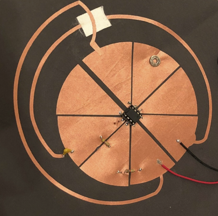
For the eTextile Spring Break I guided Martin De Bie through some iterations of his original Textilo design that includes this new thinking on layout and a further insight regarding the 8-pin DIP packages commonly used now by eTextile electronics experiments (with the ATTINY and 555 timer being common choices). This insight is to start the design from the DIP package and imagine the negative space of the smallest amount of conductive fabric that needs to be weeded to separate the 8 pins and combine the constraint of roughly equal area given to the conductors attached to each pin. This results in a motif with 8 radial lines and 8 triangles between them.
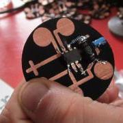
Here is the original textilo with its elegant pads to sew to:
Here is the next version with more conductive material to work with alongside the prototype of a radial design. The radial design includes serpentine interdigitation to allow for touch interaction:
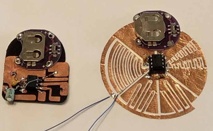
Nicole Yi Messier picked up on this radial design pattern for her wearable 555 timer based FM radio transmitter:
Pervasive Cameras: Making Sense of Many Angles using Radial Basis Function Interpolation and Salients Analysis
Abstract. This paper describes situations which lend themselves to the use of numerous cameras and techniques for displaying many camera streams simultaneously. The focus here is on the role of the “director” in sorting out the onscreen content in an artistic and understandable manner. We describe techniques which we have employed in a system designed for capturing and displaying many video feeds incorporating automated and high level control of the composition on the screen.
1 A Hypothetical Cooking Show
A typical television cooking show might include a number of cameras capturing the action and techniques on stage from a variety of angles. If the TV chef were making salsa for example, cameras and crew might be setup by the sink to get a vegetable washing scene, over the cutting board to capture the cutting technique, next to a mixing bowl to show the finished salsa, and a few varying wider angle shots which can focus on the chef's face while he or she explains the process or on the kitchen scene as a whole. The director of such a show would then choose the series of angles that best visually describe the process and technique of making salsa. Now imagine trying to make a live cooking show presentation of the same recipe by oneself. Instead of a team of camera people, the prospective chef could simply setup a bunch of high quality and inexpensive webcams in these key positions in one's own kitchen to capture your process and banter from many angles. Along with the role of star, one must also act as director and compose these many angles into a cohesive and understandable narrative for the live audience.
Here we describe techniques for displaying many simultaneous video streams using automated and high level control of the cameras' positions and frame sizes on the screen allowing a solo director to compose many angles quickly, easily, and artistically.
2 Collage of Viewpoints
Cutting between multiple view points would possibly obscure one important aspect in favor of another. In the cooking show example, a picture in picture approach would allow the display of both a closeup of a tomato being chopped and the face of the chef describing his or her cutting technique. The multi angle approach is a powerful technique for understanding all of the action being captured in a scene as well as artistically compelling and greatly simplifies the work of the director of such a scene. The multi-camera setup lends itself to a collage of framed video streams on a single screen (fig. 1 shows an example of this multi-angle approach). We would like to avoid a security camera style display that would leave much of the screen filled with unimportant content, like a view of a sink not being used by anyone.
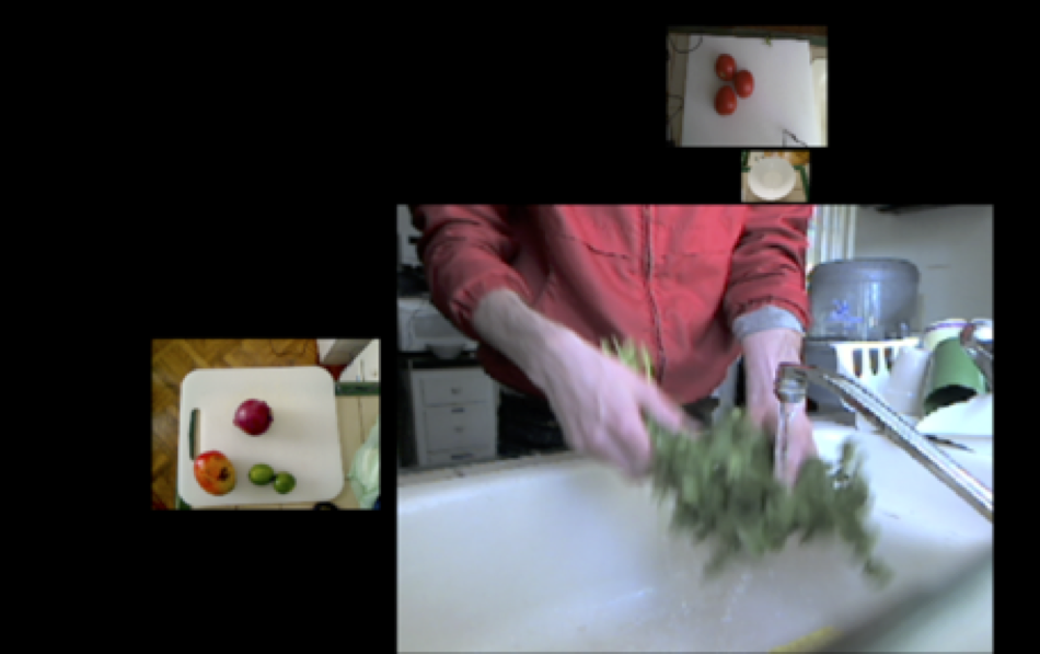
Figure 1: A shot focusing on the cilantro being washed
We focus attention on a single frame by making it larger than the surrounding frames or moving it closer to the center. The system is designed to take in a number of scaling factors (user-defined and automated) which multiply together to determine the final frame size and position. The user-defined scaling factor is set with a fader on each of the video channels. This is useful for setting initial level and biasing one frame over another in the overall mix. Setting and adjusting separate channels can be time consuming for the user, so we give a higher level of control to the user that facilitates scaling many video streams at once smoothly and quickly. CNMAT's (Center for New Music and Audio Technologies) rbfi (radial basis function interpolation) object for Max/MSP/Jitter allows the user to easily switch between preset arrangements, and also explore the infinite gradients in between these defined presets using interpolation[1]. rbfi lets the user place data points (presets in this case) anywhere in a 2 dimensional space and explore that space with a cursor. The weight of each preset is a power function of the distance from the cursor. For example, one preset point might enlarge all of the video frames on particular positions in the rooms, say by the kitchen island, so as the chef walks over the kitchen island, all of the cameras near the island enlarge and all of the other cameras shrink. Another preset might bias cameras focused on fruits. With rbfi, the user can slider the cursor to whichever preset best fits the current situation. With this simple, yet powerful high level of control, a user is able to compose the scene quickly and artistically, even while chopping onions.
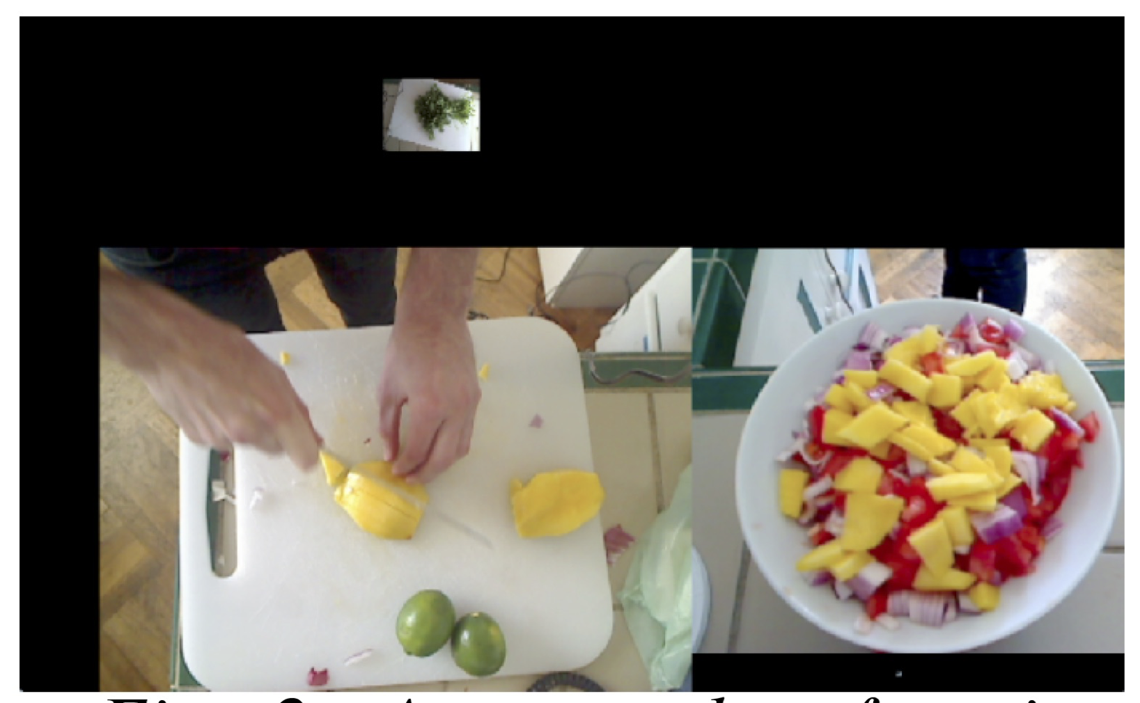
Figure 2: A screenshot focusing
on the mango being chopped and
the mixing bowl
3 Automating Control
Another technique we employ is to automate the direction of the scene by analyzing the content of the individual frame and then resizing to maximize the area of the frame containing the most salient features. This approach makes for fluid and dynamic screen content which focuses on the action in the scene without any person needing to operate the controls. One such analysis measures the amount of motion which is quantified by taking a running average of the number of changed pixels between successive frames in one video stream. The most dynamic video stream would have the largest motion scaling factor while the others shrink from their relative lack of motion. Another analysis is detecting faces using the openCV library and then promoting video streams with faces in them. The multiplied combination of user-defined and automated weight adjustment determines each frames final size on the screen. Using these two automations with the cooking show example, if the chef looks up at the camera and starts chopping a tomato, the video streams that contain the chef's face and the tomato being chopped would be promoted to the largest frames in the scene while the other less important frames shrink to accommodate the two.
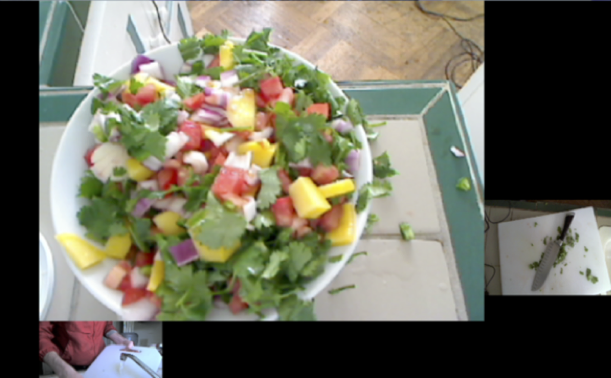 Figure 3: A screenshot of the
finished product and some
cleanup
Figure 3: A screenshot of the
finished product and some
cleanup
Positioning on the screen is also automated in this system. The frames are able to float anywhere on and off the screen while edge detection ensures that no frames overlap. The user sets the amount of a few different forces that are applied to the positions of the frames on the screen. One force propels all of the frame towards the center of the screen. Another force pushes the frames to rearrang their relative positions on the screen. No single influence dictates the exact positioning or size of any video frame; this is only determined by the complex interaction of all of these scaling factors and forces.
4 Telematic Example
Aside from a hypothetical self-made cooking show, a tested application of these techniques is in a telematic concert situation. The extensive use of webcams on the stage works well in a colocation concert where the audience might be in a remote location from the performers. Many angles on one scene gives the audience more of a tele-immersive experience. Audiences can also experience fine details like a performer's playing subtly inside the piano or a bassist's intricate fretboard work without having to be at the location or seated far from the stage. The potential issue is sorting out all of these video streams without overwhelming the viewer with content. This can be achieved without a large crew of videographers at each site, but with a single director dynamically resizing and rearranging the frames based on feel or cues as well as analysis of the video stream's content.

Figure 4: This is a view of a pianist from many angles which
would giving an audience a good understanding of the room
and all of the player's techniques inside the piano and on the
keyboard.
References
1. Freed, A., MacCallum, J., Schmeder, A., Wessel, D.: Visualizations and Interaction Strategies for Hybridization Interfaces. New Instruments for Musical Expression (2010)
Pervasive Cameras: Making Sense of Many Angles using Radial Basis Function Interpolation and Salience Analysis, , Pervasive 2011, 12/06/2011, San Francisco, CA, (2011)Rectangular grids are dominant forms in electronics and textiles. Triaxial grids have not been explored in e-textile work so this breadboard is offered to begin these explorations. Triaxial grids sample the plane with higher density and the availability of whug connections as well as warp and woof simplifies circuits by providing a natural power/ground/signal triple.
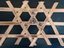
The basic 3x3x3 configuration is made by sticking conductive copper tape on strips of basket-weaving reed. This is intended to evoke the thousands of year old traditions of basket weaving and invite 3-d explorations.
Card stock is easier to procure and stick the tape to. The idea is to use a substrate that won’t burn when you solder to the tape. Substitute fabric ribbons if you are going to sew to the breadboard instead.
I used pins to lock down two of parallel rows of 3 strips and then slid in the final row, guiding them over and under as required. The example has charlieplexed LED’s soldered on but this is just to start you thinking about how you might use such a dense array of available conductors.
Consider replacing a central strip with one with copper tape on both sides. Work out which conductors are then connected. Now consider sandwiching piezoresistive fabric between intersecting conductors. Can you use this to read an array of pressures sensors?
References/Inspirations:
core memory beading
triaxial textiles
basket weaving
multitouch
Materials: Cane, copper tape
Techniques: Weaving
The provided swatches will just be the breadboard. Illustrated are some LED’s controlled by Charlieplexing.
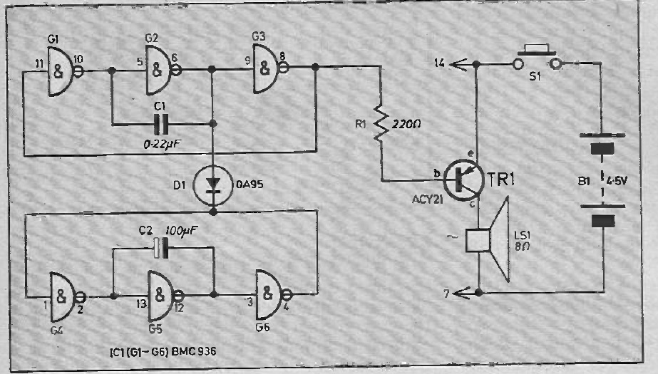
Circuit Diagram:
http://www.pcbheaven.com/wikipages/Charlieplexing/