- David Wessel’s IRCAM
- Organized Entanglement: Fiber and Textile Arts, Science and Engineering
- Managing Complexity with Explicit Mapping of Gestures to Sound Control with OSC
- Notations for Performative Electronics: the case of the CMOS Varactor
- A Synthesizable Hybrid VCO using SkyWater 130nm Standard-Cell Multiplexers
- A Recipe using OSC Messages
- Birds of the East Bay 2020
- Exercising the odot language in Graphics Animation Applications
- C++ container output stream header file
- Programming
A Synthesizable Hybrid VCO using SkyWater 130nm Standard-Cell Multiplexers

Summary
I introduce a new synthesizable VCO using (n+1) mux2i cells from the SkyWater130 PDK to form a (2n+1) hybrid ring oscillator.Introduction
The benefits of alternating current-starved and regular inverters in a ring oscillator have been observed for at least a decade [1] and carefully analyzed here: [2]. A key benefit is a consequence of the observation that propagation delay of a regular inverter is inversely proportional to VDD and is proportional to VDD for the current-starved inverter [3].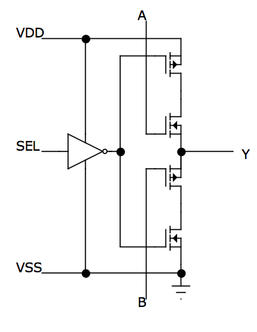
Although it is possible to make current-starved inverters using nand2 cells, for example, it's difficult to balance the output because most standard cell logic realizations are asymmetric combinations of series and paralled transistors. Voltage control range is limited with nand cells compared to balanced current-starved inverters.
Skywater130 mux2i
The SkyWater130 PDK has 7 factory, standard cell libraries with different performance tradeoffs. 6 of them provide a mux2i cell with a useful design for these purposes (High Speed, Medium Speed, Low Speed and Low Power, High Density and High Density Low Leakage). A separate inverter is provided for each multiplexed input. Their outputs are connected. The active inverter is chosen in digital applications by power switching the sources of its complementary transistors:This employs an inverter from the "select" input.
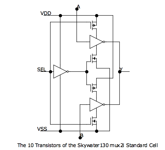
If the inputs to each inverter are connected to positive and negative voltage control bias sources, the resulting circuit approximates quite well the primary module used of a hybrid ring oscillator where an inverter and a current-starved inverter are combined. An additional mux2i is used with the positive and negative voltage rails exchanged to form the extra inverter needed for oscillation .
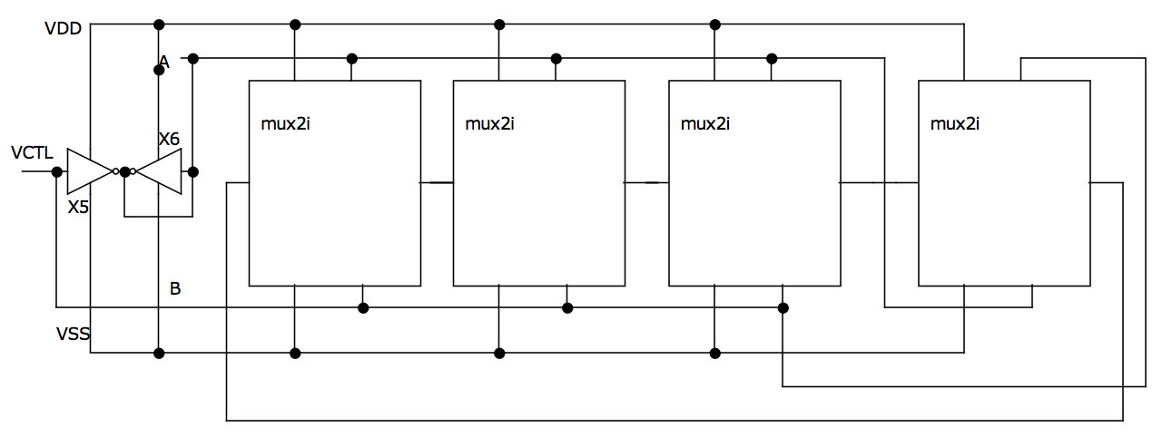
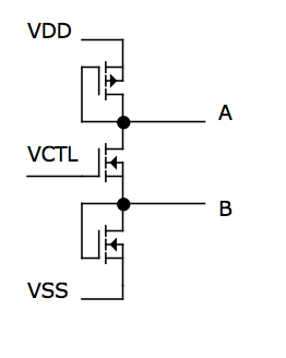
The usual bias source for this kind of oscillator involves another configuration not obtainable with standard cells.
This was replaced with the synthesizable, inverting voltage follower made from two equally-sized inverters.
An alternative to using the mux2i cell with swapped bias inputs is to make one of the cells using the mux2 cell which adds an inverter
to the same layout as a mux2i cell.
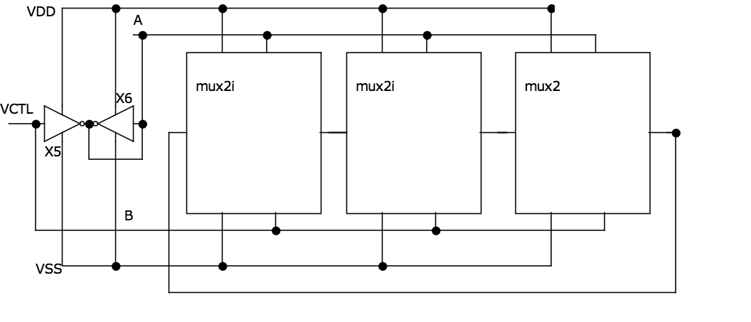
For the 7th Skywater130 High-Voltage library without a mux2i the same technique may be adapted using the positive and negative enable tristate buffers, einvp and einvn.
Performance
This standard cell oscillator will likely be slightly inferior to a custom layout in most parameters except design time and cost. It uses (10n +10) vs (6n+2) transistors or-in the case of the mux2 version-(10n+2) vs (6n+2), The additional transistors may have a role in slowing the oscillator down or reducing its frequency range. 1GHz was readily achieved in prelayout Spice simulations with the High Speed cells.Voltage control can be observed in the following simulation output:
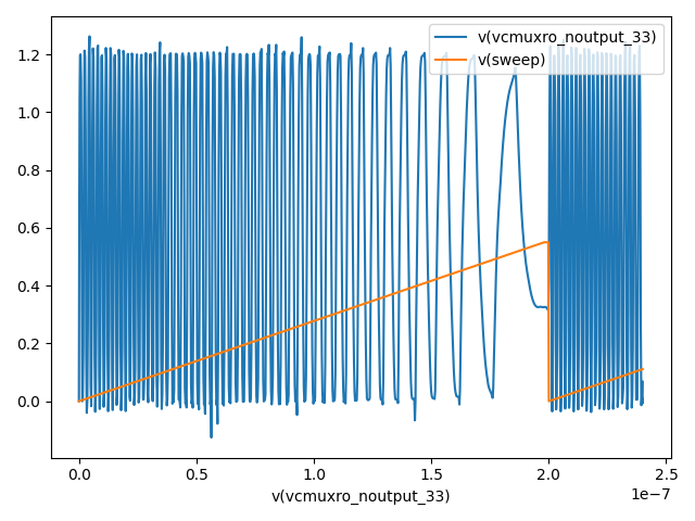
The inverting voltage follower bias generator may have higher current consumption than an optimized bias generator. However, since this new design can be synthesized so easily and implemented in multiple libraries on Skywater130, it may serve as a useful benchmark of those libraries.
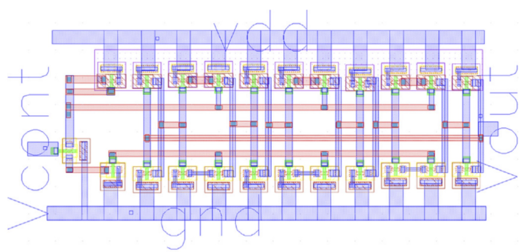
It would be useful to design a benchmark comparison by following the basic layout in [4].
[1]A CMOS Voltage Controlled Ring Oscillator with Improved Frequency Stability, Goran Jovanovic, Mile Stojcev, Zoran Stamenkovic, Scientific Publications of the State University of Novi Pazar, Ser. A: Appl. Math. Inform. and Mech, Vol. 2, pp. 1-9, 2010.
[2]CMOS ring oscillator with combined delay stages, Ramazani, A., Biabani, S., & Hadidi, G. (2014), AEU-International Journal of Electronics and Communications, 68(6), 515-519.
[3] Improved accuracy equation for propagation delay of a CMOS inverter in a single ended ring oscillator, Zafarkhah, E., Maymandi-Nejad, M., & Zare, M., 2017, AEU - International Journal of Electronics and Communications, 71, 110-117.
[4] A 46.8 microW/1.12 GHz 7th Stage New Ring Voltage Controlled Oscillator, Madhusudan Maiti, Suraj Kumar Saw, Vijay Nath, Swarnendu Kumar Chakraborty and Alak Majumder, V. Nath and J. K. Mandal (eds.), Nanoelectronics, Circuits and Communication Systems, Lecture Notes in Electrical Engineering 642,
- AdrianFreed's blog
- Login or register to post comments
- Printer-friendly version

Comments