Realized by Martin De Bie
Circuit Layout Design Patterns for eTextiles Appliqués with Conductive Fabric
Sun, 04/22/2018 - 16:34 — AdrianFreedThis style is not convenient for eTextile Appliqués which are most commonly single-sided and are based on cut traces rather than etched boards.
There is an older style of PCB layout that is more suitable for low-speed e-textiles that I remember seeing with old transistor radios. The style is almost all copper with just a few lines etched away to separate conductors.
This makes designs more robust with multiple parts soldered on and removed and with multiple sewing points at the edges.
It also makes for less weeding and more surface area that will be fused/glued to the base fabric.

It was also common for many of the traces in these radios to be curved.
For the eTextile Spring Break I guided Martin De Bie through some iterations of his original Textilo design that includes this new thinking on layout and a further insight regarding the 8-pin DIP packages commonly used now by eTextile electronics experiments (with the ATTINY and 555 timer being common choices). This insight is to start the design from the DIP package and imagine the negative space of the smallest amount of conductive fabric that needs to be weeded to separate the 8 pins and combine the constraint of roughly equal area given to the conductors attached to each pin. This results in a motif with 8 radial lines and 8 triangles between them.
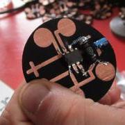
Here is the original textilo with its elegant pads to sew to:
Here is the next version with more conductive material to work with alongside the prototype of a radial design. The radial design includes serpentine interdigitation to allow for touch interaction:
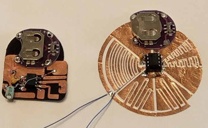
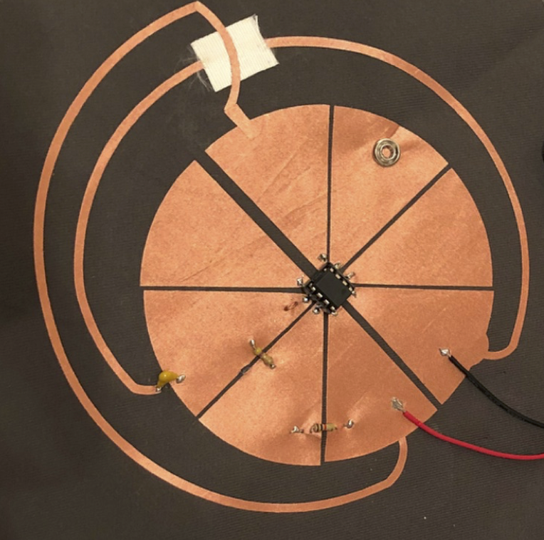
Nicole Yi Messier picked up on this radial design pattern for her wearable 555 timer based FM radio transmitter:
Textile 555 Oscillator ElectroSomatophone for circuit bending
Thu, 04/12/2018 - 16:39 — AdrianFreed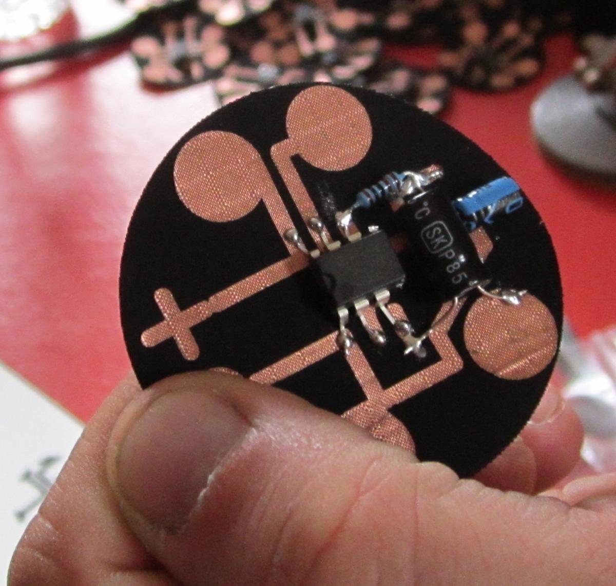
I tested this CMOS 555 breadboard version.
This informed suggested improvements to Textilo to Martin who came up with a textile layout which we used to teach during the audio workshop of e-textile Spring Break: http://youtube.com/HdMsk6c3WGw
Alex blogged a great student perspective of this workshop.
I also brought along some PCB's which can be sewed to or pressed on Lego baseboards.
To address the need for more interaction room for the fingers I suggested to Martin to look at a radiating octagonal design. He prototyped this at the camp in copper:
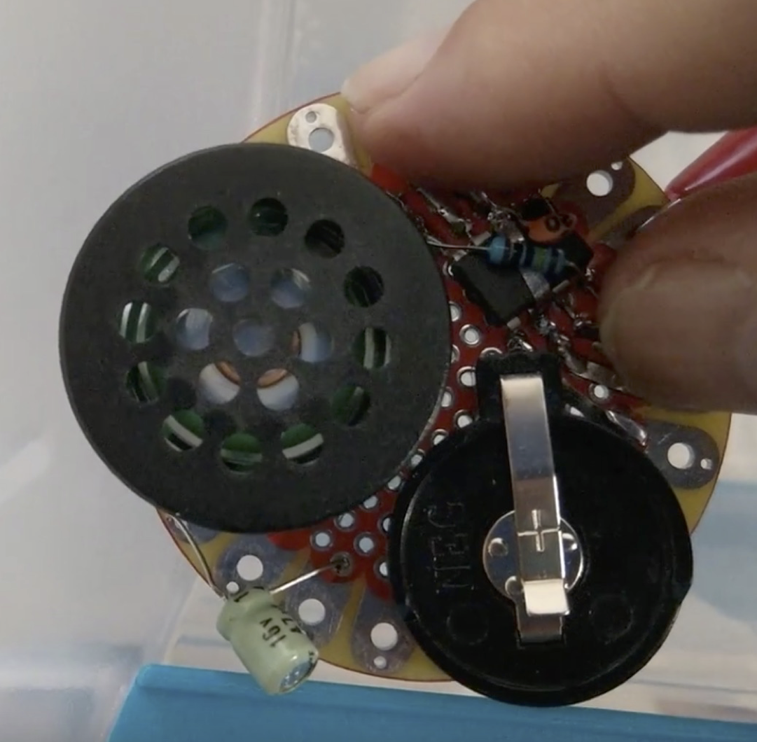
Nicole Messier also picked up on this design pattern and made a 555 oscillator based FM Radio transmitter:
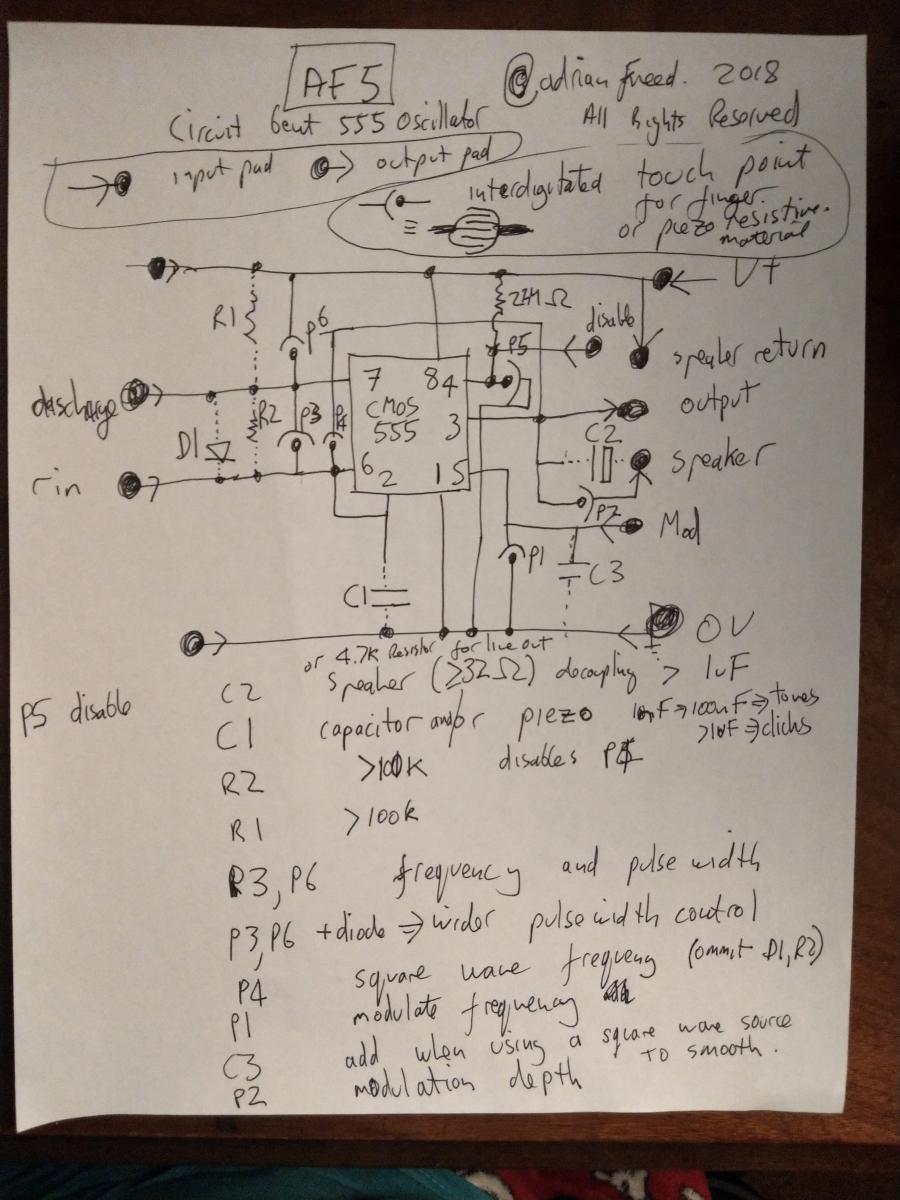
A walk through the schematic may be helpful.
Now what makes things productively confusing is the absence of resistors in the story. These are provided by your fingers or additional LDRs or piezoresistive fabrics. The layout is designed to give you room to put fingers in the useful places for the two popular ways of making the 555 timer oscillator. One way creates square waves. The other makes controllable pulse waves. I capture these possibilities on the following schematic which has a special notation for where you add variable resistance: