Put a 9-DoF Sensor Inside a Wii Nunchuck: 3D Orientation on Its Own Cable
Series: alt.ctrl activities; builds on Wii controllers
The Wii Nunchuck fits one hand: a joystick under the thumb, two buttons under the fingers, and an accelerometer inside. Held still, the accelerometer gives its tilt, but not the direction it points around the vertical, and in motion it cannot tell tilt from movement. A small 9-DoF board inside the shell adds what the hand does as it turns: a gyroscope's angular velocity on three axes and a magnetometer's reading of the magnetic field, which the microcontroller fuses with the accelerations into a 3D orientation.
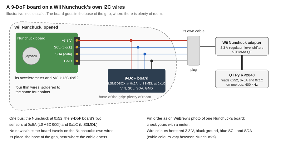
The Nunchuck's cable already carries an I2C bus (power, ground, SDA and SCL), on which the Nunchuck answers at the fixed address 0x52. Devices with other addresses can share those wires, so a 9-DoF board soldered to the same four points inside, its two sensors at 0x6A and 0x1C, travels on the Nunchuck's own cable and plug: no new cable, and the joystick, buttons and accelerometer read as before.
The board here is Adafruit's LSM6DSOX + LIS3MDL: two sensors on plain register-based I2C, with an example in Adafruit's AHRS library that calibrates and fuses exactly this pair. Its accelerometer and gyroscope sample at up to 6.7 kHz; the orientation is as fresh as the microcontroller makes it, 100 times a second in Adafruit's example. A board with a BNO085, which fuses on its own chip, fits a shared bus badly: polled with no data ready, it holds the clock line low (its datasheet), and it works poorly with several microcontrollers and through I2C multiplexers (Adafruit's guide).
Materials
| Item | Amazon | Adafruit | Mouser |
|---|---|---|---|
| A wired Wii Nunchuck | 342 | 485-342 | |
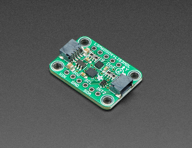 | 4517 | 485-4517 | |
| Or, cheaper: a GY-85 nine-axis module, with an ITG3205 gyroscope, an ADXL345 accelerometer and an HMC5883L magnetometer at I2C 0x68, 0x53 and 0x1E; 28.4 × 15.2 mm and 3.3 to 5 V by the listing. Adafruit's AHRS library has no ready example for it: see the variations | B0FKMWKB77 |
| Item | Amazon | Adafruit | Mouser |
|---|---|---|---|
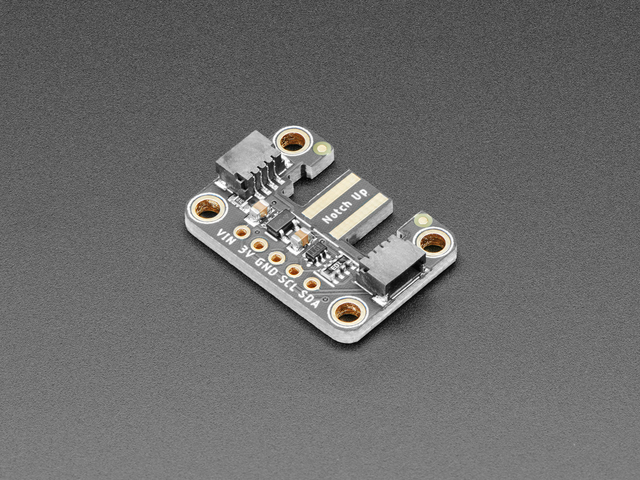 | 4836 | 485-4836 | |
| Adafruit QT Py RP2040, or another microcontroller board with a STEMMA QT port: Adafruit's AHRS guide recommends a Cortex-M0 or faster for the fusion | 4900 | 485-4900 | |
| A STEMMA QT / Qwiic cable, 100 mm | 4210 | 485-4210 | |
| Thin, flexible insulated wire, in four colours | |||
| Polyimide (Kapton) tape, to insulate the back of the board, and double-sided foam tape to hold it |
Tools
- A tri-point Y0 screwdriver, for the two screws on the Nunchuck's back (iFixit's guide uses one)
- A spudger or a thin plastic pry tool
- A soldering iron with a fine tip, and solder
- Flush cutters and wire strippers
- A multimeter with a continuity test
- MotionCal, on a computer, for the magnetometer's calibration (Adafruit's AHRS guide)
- An MCU IDE: the Arduino IDE, or CircuitPython
Skills
- Soldering fine wires to small pads
- Using a multimeter's continuity test
- Connecting I2C (Qwiic / STEMMA QT) boards
- Programming an MCU in Arduino or CircuitPython
Instructions
- Before opening the Nunchuck, try it as it is: plug it into the adapter, notch up as the adapter is marked, connect the adapter to the QT Py RP2040 with the STEMMA QT cable, and run an I2C scan. The Nunchuck answers at 0x52. Read its joystick, buttons and accelerometer with the WiiChuck library (Arduino) or adafruit_nunchuk (CircuitPython).
- Open the Nunchuck: take out the two tri-point screws on its back, and ease the top half of the case off, starting near the joystick, as iFixit's guide shows.
- Find where the cable joins the Nunchuck's circuit board. On the board WiiBrew photographs, it is a four-pin connector whose pins are, in order, +3.3 V, clock (SCL), data (SDA) and ground. Check yours with the meter's continuity test, from each contact of the unplugged plug (WiiBrew's photo of the plug names them) to the pins inside. Do not go by the wires' colours.
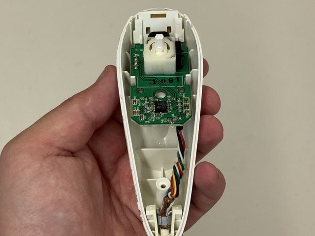
- Find the board's place in the base of the grip, between the circuit board and where the cable comes in: there is plenty of room there for the board, 25.4 × 17.8 × 4.5 mm by Adafruit's CAD model. The photo below shows that space in one Nunchuck, mostly empty: the cable's wires run up one side, and a screw post stands near where the cable enters.
- Solder four thin wires from the board's VIN, GND, SCL and SDA to the back of the same four pins, or to the pads where the cable's wires are soldered. Leave the board's other pins, and its address jumpers, as they are.
- Cover the back of the board with polyimide tape, fix it in the base of the grip with double-sided foam tape, clear of the screw post, and route the wires clear of the joystick and buttons. Note which way the board's X, Y and Z axes point in the Nunchuck, for the program.
- Close the case, and check that the joystick and both buttons still move freely.
- Plug the Nunchuck back into the adapter and scan again: now 0x52, 0x6A and 0x1C all answer.
- Calibrate the magnetometer with the board closed inside the Nunchuck, since what is near it changes what it reads. Adafruit's AHRS guide does it with Paul Stoffregen's MotionCal and stores the result on the microcontroller: "Calibrating the magnetometer is required to get good orientation data!"
- Fuse and read: the calibrated_orientation example of Adafruit's AHRS library combines the gyroscope, accelerometer and magnetometer into an orientation with the Mahony, Madgwick or NXP filter (switch its sensor file from the LSM6DS33 to the LSM6DSOX), and the Nunchuck is read on the same bus. The Coding Prompt Build Block below spells this out.
- Map them to sound: the joystick and buttons as before, and now the turning of the hand too.
Variations
- Measure the gain: log the Nunchuck's accelerations and the 9-DoF board's readings side by side, with timestamps, and count how often each changes. Raise the fusion rate above Adafruit's 100 a second and see how far the microcontroller keeps up.
- Leave out the magnetometer near speakers, motors or steel: the Mahony and Madgwick filters also update from the gyroscope and accelerometer alone (updateIMU), so the orientation no longer follows the magnetic field, and its heading slowly drifts instead.
- Two augmented Nunchucks: the Nunchucks both answer at 0x52 and their 9-DoF boards share addresses too, so put each Nunchuck on its own channel of an I2C multiplexer, as the Universal Platform for Frankensteining Controllers does with its PCA9548.
- A cheaper board, the GY-85 in the materials: its chips answer at 0x68, 0x53 and 0x1E, clear of the Nunchuck's 0x52, so it joins the same four wires. Read the ADXL345 and the HMC5883L with Adafruit's ADXL345 and HMC5883 Unified libraries and the ITG3205 gyroscope from the registers its datasheet gives, then feed the same Mahony or Madgwick filter, which takes raw values. Some GY-85 boards carry a QMC5883L magnetometer instead, at 0x0D, which needs its own library: an I2C scan tells which.
Related resources
- Wiimote, Nunchuck and Inertial Sensor Hacking for Music and other Interactivity, a 2009 presentation at Hexagram/Concordia, Montreal: Wiimote alternatives such as the Gametrak, Nunchucks to uOSC, and gesture signal processing in Max/MSP
- Make a Universal Platform for Frankensteining Controllers, a base that reads two Nunchucks and many other controllers
- Nunchuk and Extension Controllers (WiiBrew): the Nunchuck's data format, parts and board, its I2C address and initialisation, and photos of its board's connector and of the plug's contacts
- ST 9-DoF Combo Breakouts and Wings (Adafruit Learn): the board's pins, addresses and libraries
- How to Fuse Motion Sensor Data into AHRS Orientation (Euler/Quaternions) (Adafruit Learn): calibration with MotionCal, and the Mahony, Madgwick and NXP filters
- Adafruit Wii Nunchuck Breakout Adapter (Adafruit Learn)
- Wii Nunchuk Joystick and Button Replacement (iFixit): opening the case
Coding Prompt Build Block
A prompt to give a coding assistant, to start the code for this activity. Copy the box, answer its questions about your board and pins, and test what comes back on the bench before you rely on it.
I am building "Put a 9-DoF Sensor Inside a Wii Nunchuck: 3D Orientation on Its Own Cable", the activity at https://adrianfreed.com/wii-nunchuck-9dof-inside.html.
Write a program for a microcontroller (an RP2040 board here) that reads a Wii Nunchuck and a 9-DoF board, an LSM6DSOX accelerometer and gyroscope with an LIS3MDL magnetometer, sharing one I2C bus at 400 kHz: the Nunchuck answers at address 0x52, the LSM6DSOX at 0x6A and the LIS3MDL at 0x1C. Scan the bus first and report which addresses answer.
Initialise the Nunchuck by writing 0x55 to its register 0xF0 and then 0x00 to its register 0xFB, so its data is unencrypted. Then read its six bytes again and again: the joystick's X and Y, the three 10-bit accelerations, and the C and Z buttons.
Read the LSM6DSOX's accelerations and angular velocities and the LIS3MDL's magnetic field. Apply the magnetometer's calibration (its hard- and soft-iron corrections, measured with MotionCal with the board closed inside the Nunchuck) and the gyroscope's zero offsets, and fuse the three into an orientation with the Mahony or Madgwick filter at a fixed rate, 100 times a second to start, with the sensors' data rates set a little above it. Make the magnetometer optional: without it, fuse only the gyroscope and accelerometer.
Send everything as OSC over USB serial, framed with SLIP: the joystick, the buttons and the Nunchuck's accelerations, and the 9-DoF board's quaternion, yaw, pitch and roll, angular velocities and magnetic field, each message with a timestamp, so that the two sensors' rates can be compared. Leave the mapping to sound to the program that receives them.
Libraries to explore:
- WiiChuck: reads Wii extension controllers over I2C (the Nunchuck, Classic Controller, Guitar Hero guitar and drums, DJ Hero, Drawsome tablet and Taiko drums), all mapped into one array of values (https://github.com/madhephaestus/WiiChuck)
- Adafruit LSM6DS: Arduino library for the LSM6DS family of accelerometer and gyroscope chips, the LSM6DSOX among them; it needs Adafruit BusIO and Adafruit Unified Sensor (https://github.com/adafruit/Adafruit_LSM6DS)
- Adafruit LIS3MDL: Arduino library for the LIS3MDL magnetometer (https://github.com/adafruit/Adafruit_LIS3MDL)
- Adafruit AHRS: fuses an accelerometer, gyroscope and magnetometer into an orientation with the Mahony, Madgwick or NXP filter (updateIMU leaves out the magnetometer); its calibrated_orientation example has a ready sensor file for the LSM6DS and LIS3MDL pair (https://github.com/adafruit/Adafruit_AHRS)
- Adafruit Sensor Calibration: keeps a sensor's calibration in the microcontroller's EEPROM or flash, for the AHRS examples (https://github.com/adafruit/Adafruit_Sensor_Calibration)
- OSC for Arduino (CNMAT): encodes and decodes OSC messages, and sends them over USB or hardware serial (framed with SLIP) or over Ethernet and Wi-Fi UDP; its Applications folder has Max/MSP and Pd examples that receive them (https://github.com/CNMAT/OSC)
- Adafruit CircuitPython Nunchuk: reads the Wii Nunchuck (Wiichuck) in CircuitPython (https://github.com/adafruit/Adafruit_CircuitPython_Nunchuk)
- Adafruit CircuitPython LSM6DS: reads the LSM6DS family in CircuitPython (https://github.com/adafruit/Adafruit_CircuitPython_LSM6DS)
- Adafruit CircuitPython LIS3MDL: reads the LIS3MDL magnetometer in CircuitPython (https://github.com/adafruit/Adafruit_CircuitPython_LIS3MDL)
Before writing anything, ask me what I am using: the board and its pins, or the software (such as Max, Pd or Python), and check its documentation for what this needs. Put the pin numbers, ranges and other settings in one block at the top, each with a comment. Say which of the libraries above you use, and why. Start with a test that shows the raw readings, so that I can check the wiring and the ranges before the rest.
This activity by Adrian Freed is licensed under Creative Commons Attribution-NonCommercial-ShareAlike 4.0 International (CC BY-NC-SA 4.0): you may share and adapt it with attribution, for non-commercial purposes such as personal projects and teaching, and you must share adaptations under the same licence. Product names and links belong to their suppliers. The photos are not covered by this licence: each keeps the licence named in its credit.