Make a Universal Platform for Frankensteining Controllers
Series: alt.ctrl activities; builds on Wii controllers and Game controllers
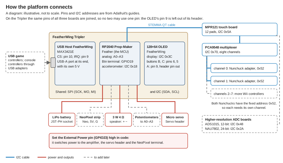
A base for Frankensteining controllers: one stack of boards that reads many kinds of controller and sensor at once, and drives a speaker, a servo, LEDs and a display from them. It starts with two Wii Nunchucks, a capacitive touch board and the display's buttons, and grows into USB game controllers, console controllers, knobs, high-resolution sensors, and M5Stack's 5 V Grove units: arrays of potentiometers, encoders, switches and buttons, and a keyboard.
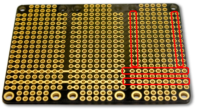
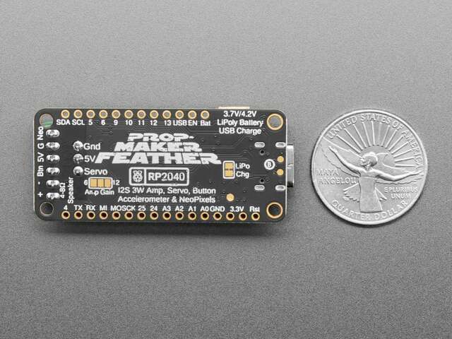
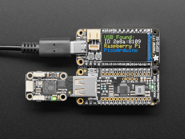
Three boards sit side by side on a FeatherWing Tripler, which joins the same pins of all three: an RP2040 Prop-Maker Feather (the microcontroller, with a 3 W amplifier, a servo header and a NeoPixel terminal), a USB Host FeatherWing, and a 128×64 OLED FeatherWing. No two may use the same pin: the USB Host FeatherWing uses pins 10 (CS) and 9 (IRQ) with the SPI pins; the OLED display, like every Qwiic board here, is on I2C, and its buttons B and C are on pins 6 and 5. Its button A is on pin 9 too, so that one header pin is left out of the OLED FeatherWing.
Materials
| Item | Amazon | Adafruit | Mouser |
|---|---|---|---|
 | 3417 | 485-3417 | |
 | 5768 | 485-5768 | |
 | 5858 | 485-5858 | |
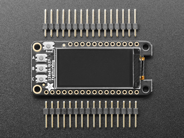 | 4650 | 485-4650 | |
| A large lithium-ion polymer battery with Adafruit's JST-PH plug and polarity, such as the 3.7 V 2500 mAh | 328 | 485-328 | |
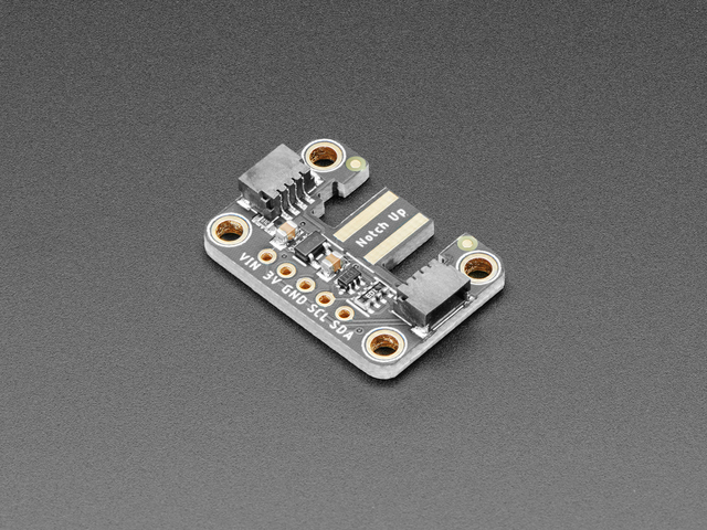 | 4836 | 485-4836 | |
| Two Wii Nunchuck controllers | 342 | 485-342 | |
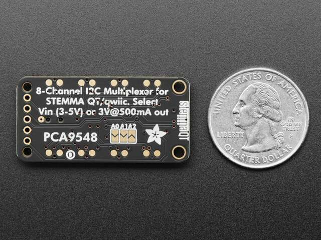 | 5626 | 485-5626 | |
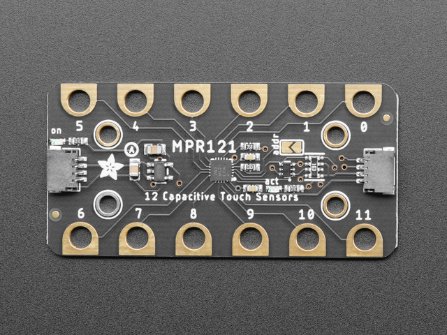 | 4830 | 485-4830 | |
| Four STEMMA QT / Qwiic cables, 100 mm | 4210 | 485-4210 | |
| A 3 W, 4 Ω enclosed speaker (this one ends in a JST-PH plug, to cut off for the screw terminals) | 3351 | 485-3351 | |
| A micro servo (TowerPro SG92R; 4.8 V nominal, 3 to 6 V) | 169 | 485-169 | |
| A USB-C data cable, for programming |
| Item | Amazon | Adafruit | M5Stack | Mouser | Digi-Key |
|---|---|---|---|---|---|
| NeoPixel LED strip, 30 LEDs per metre, 1 m | 2552 | 1528-2552-ND | |||
| Other Wii extension controllers: the Classic Controller, Guitar Hero guitars and drums, DJ Hero, the Drawsome tablet, Taiko drums (one more Nunchuck adapter each) | |||||
| A USB game controller, such as this generic one with an SNES-like layout | 6285 | 485-6285 | |||
| Adapters that connect other consoles' controllers over USB | |||||
| 10 kΩ linear potentiometers | 562 | 485-562 | |||
| ADS1015 12-bit ADC, four channels with a programmable gain amplifier (STEMMA QT / Qwiic) | 1083 | 485-1083 | |||
| NAU7802 24-bit ADC, for load cells, strain gauges and other bridge sensors (STEMMA QT / Qwiic) | 4538 | 485-4538 | |||
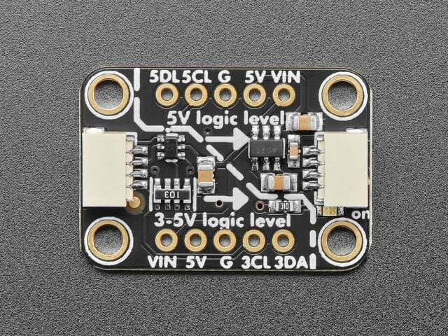 | 5649 | 485-5649 | |||
| A Grove to STEMMA QT / Qwiic cable, 100 mm: from the booster's 5V port to a Grove unit | 4528 | 485-4528 | |||
| M5Stack 8-Angle Unit: eight potentiometers and a switch (I2C 0x43) | U154 | 170-U154 | |||
| M5Stack 8-Encoder Unit: eight rotary encoders and a switch (I2C 0x41) | U153 | 170-U153 | |||
| M5Stack Byte Switch Unit: eight toggle switches, and a second Grove port that passes the bus on (I2C 0x46) | U191 | 170-U191 | |||
| M5Stack Byte Button Unit: eight buttons (I2C 0x47) | U192 | 170-U192 | |||
| M5Stack CardKB v1.1: a card-sized 50-key QWERTY keyboard (I2C 0x5F) | U035-B | 170-U035-B | |||
| M5Stack 1 to 3 HUB Expansion Unit: one Grove port to three | U006 | 170-U006 |
Tools
- Soldering iron and solder
- Flush cutters and wire strippers
- A small flat screwdriver, for the screw terminals
- An MCU IDE: the Arduino IDE, with the Adafruit TinyUSB library for the USB host
Skills
- Soldering header pins and sockets
- Connecting I2C (Qwiic / STEMMA QT) boards
- Programming an MCU in Arduino
Instructions
- Solder the three sets of female header sockets that come with the FeatherWing Tripler onto its three rows of pads.
- Solder the male header strips that come with the RP2040 Prop-Maker Feather, the USB Host FeatherWing and the OLED FeatherWing onto each board. Before soldering the OLED FeatherWing's strip for the 12-pin side, pull out the pin for pin 9, the fifth from the SDA end (the Feather's order there is SDA, SCL, 5, 6, 9, 10, 11, 12, 13, USB, EN, BAT). The OLED's button A is on pin 9, which is also the USB Host FeatherWing's IRQ line, driven push-pull by the TinyUSB driver: connected, the button would short that output to ground.
- Plug the three boards into the Tripler's sockets.
- Plug the battery into the Prop-Maker Feather's JST-PH battery socket. Its polarity is matched to Adafruit's batteries: Adafruit warns that a battery of the wrong polarity can destroy the Feather, so check any other.
- Connect the speaker to the Prop-Maker Feather's + and − terminals: cut off its plug, strip the two wires and screw them in.
- Plug the servo into the Prop-Maker Feather's three-pin Servo header: its orange signal wire to Sig, its power wire to V+ and its ground wire to G.
- Chain the I2C boards with STEMMA QT cables: from the Prop-Maker Feather's STEMMA QT port to the MPR121 touch board, from the MPR121's other port to the PCA9548 multiplexer, and from two of the multiplexer's channels to the two Nunchuck adapters. Plug each Nunchuck into its adapter, as the adapter's "Notch Up" marking shows.
- Set up the Arduino IDE for the RP2040 Prop-Maker Feather and install the Adafruit TinyUSB library. The USB Host FeatherWing's examples use pin 10 for CS and pin 9 for IRQ; on the RP2040, do not include pio_usb.h, or the library uses the RP2040's own PIO USB host instead of the MAX3421E. Arduino is the way to the USB host here: CircuitPython for this Feather has no max3421e module.
- In your code, set the External Power pin (GPIO23) high before using the speaker, the servo or the NeoPixel terminal: they have no power until it is.
- Test each part with the example in its Learn guide: the display (Adafruit SH110X library, I2C address 0x3C) and its buttons B and C (pins 6 and 5), the touch board (Adafruit MPR121), the Nunchucks (WiiChuck, selecting each one's multiplexer channel before reading it), the servo, and sound through the I2S amplifier.
- Then use it as a platform. Add LED strings: connect a NeoPixel strip's data, 5 V and ground to the Prop-Maker Feather's Neo, 5V and G terminals; a level shifter gives the data line 5 V. The terminal takes its power from the battery or USB, whichever is higher, so mind the current: Adafruit rates its 30-LED-per-metre strip at about 2 A per metre at full white.
- Add more Wii controllers: the Nunchuck adapter also takes the Classic Controller, Guitar Hero guitars and drums, DJ Hero, the Drawsome tablet and Taiko drums (the WiiChuck library's list). Each needs its own multiplexer channel; one PCA9548 has eight.
- Add USB PC game controllers: plug them into the USB Host FeatherWing's USB-A port. The Adafruit TinyUSB library's hid_device_report example prints the reports a controller sends, for your code to decode. Adafruit notes that, beyond a generic mouse, keyboard, serial or storage device, a USB device needs a driver that knows it.
- Add game controllers from consoles through USB adapters that connect them as USB devices, and read them the same way.
- Add potentiometers straight to the RP2040's four 12-bit analog inputs, A0 to A3: the two outer legs to 3.3V and GND, the wiper to an analog pin.
- Add higher-resolution analog sources through Qwiic ADC boards on the I2C chain: the ADS1015, 12 bits on four inputs or two differential pairs, at I2C 0x48 (or 0x49 to 0x4B by jumper), and the NAU7802, 24 bits for load cells and other bridge sensors, at the fixed address 0x2A (more than one goes on the multiplexer).
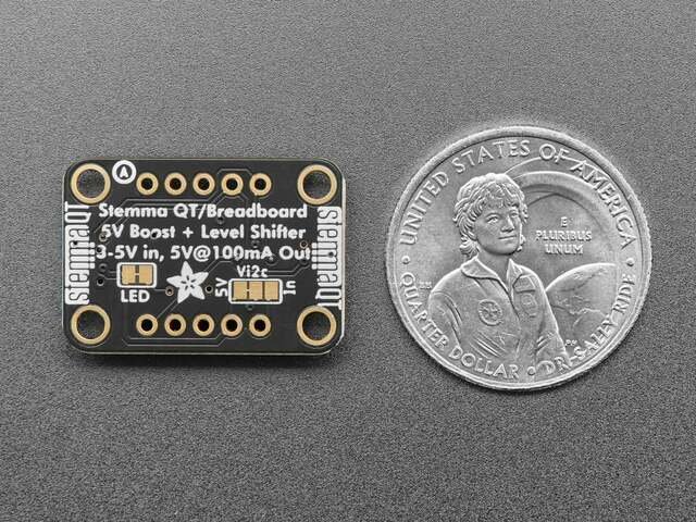
- Add M5Stack's Grove units through the QT 3V to 5V Level Booster: the 8-Angle (eight potentiometers, I2C 0x43), the 8-Encoder (eight rotary encoders, 0x41), the Byte Switch (eight toggle switches, 0x46), the Byte Button (eight buttons, 0x47) and the CardKB keyboard (0x5F); none of these addresses is used by the boards above. They take 5 V from the Grove port, but the 8-Angle, 8-Encoder, Byte Switch and Byte Button run on 3.3 V inside and pull SDA and SCL up to that 3.3 V (their schematics), and the CardKB works with 3.3 V I2C too. So first cut the trace of the 5V jumper under Vi2c on the booster's back, which sets "the output logic level to unshifted 3V" while its 5V port still carries 5 V (Adafruit's guide). Plug the booster's 3V port, the one behind the arrows on its silkscreen, into a free channel of the PCA9548 multiplexer, so that the units and their pull-up resistors have a bus segment of their own, and select that channel in your code before talking to them. Run a Grove to STEMMA QT cable from the booster's 5V port to the first unit. The Byte Switch passes the bus on through its second Grove port; a 1 to 3 HUB Expansion Unit splits it for units with one port. The booster gives 100 mA continuous, so add up the units' draw, their RGB LEDs included: M5Stack gives only the Byte Switch's standby draw, 9.03 mA at 5 V.
- For anything else, the terminal block's Btn connection (GPIO19, a digital input or output) is free when no button is wired to it, and these boards leave header pins 11, 12, 24, 25, RX and TX unused.
Variations
- A color display: the Mini Color TFT with Joystick FeatherWing (Adafruit 3321) in place of the OLED, a 0.96" 160×80 display with a 5-way joystick and two buttons read over I2C (seesaw, address 0x5E). Its CS and DC are pins 5 and 6, so no header pin needs leaving out.
- A bigger battery: Adafruit's 3.7 V 4400 mAh Li-ion pack (354) runs longer, but it charges slowly from the Feather's built-in charger, which Adafruit gives as "200mA+".
- More Nunchucks, Wii controllers or NAU7802s: each takes one of the multiplexer's eight channels, and jumpers set the multiplexer's address from 0x70 to 0x77 for more multiplexers.
- Larger touch surfaces clipped to the MPR121's pads with alligator clips: Adafruit suggests copper foil, metallic nylon or Pyralux. For touch on crocheted conductive thread, see Headpieces That Sound Through Touch.
Related resources
- Adafruit RP2040 Prop-Maker Feather (Adafruit Learn): pinouts, the External Power pin, power
- Adafruit USB Host FeatherWing with MAX3421E (Adafruit Learn), and the Adafruit TinyUSB library
- Adafruit 128x64 OLED FeatherWing and Adafruit Mini TFT with Joystick Featherwing (Adafruit Learn)
- FeatherWing Proto, Doubler and Tripler (Adafruit Learn)
- Adafruit Wii Nunchuck Breakout Adapter (Adafruit Learn), and the WiiChuck library
- Adafruit PCA9548 8-Channel STEMMA QT / Qwiic I2C Multiplexer (Adafruit Learn)
- Adafruit MPR121 12-Key Capacitive Touch Sensor Gator Breakout (Adafruit Learn)
- Adafruit NeoPixel Überguide (Adafruit Learn)
- Adafruit 4-Channel ADC Breakouts (the ADS1015) and Adafruit NAU7802 24-Bit ADC - STEMMA QT / Qwiic (Adafruit Learn)
- Wiimote, Nunchuck and Inertial Sensor Hacking for Music and other Interactivity: the owner's talk on interfacing Nunchucks
- Other activities: Intervene in USB Controller I/O Streams with an MCU Interposer, Replace the Gametrak's Electronics
Coding Prompt Build Block
A prompt to give a coding assistant, to start the code for this activity. Copy the box, answer its questions about your board and pins, and test what comes back on the bench before you rely on it.
I am building "Make a Universal Platform for Frankensteining Controllers", the activity at https://adrianfreed.com/universal-platform-frankensteining-controllers.html.
Write an Arduino program for an Adafruit RP2040 Prop-Maker Feather on a FeatherWing Tripler with a USB Host FeatherWing (MAX3421E: CS on pin 10, IRQ on pin 9; do not include pio_usb.h, or the library uses the RP2040's own PIO USB host instead) and an OLED FeatherWing (SH1107 at I2C address 0x3C; buttons B and C on pins 6 and 5). On the STEMMA QT chain: an MPR121 touch board, and a PCA9548 I2C multiplexer with a Wii Nunchuck adapter on each of two channels (both Nunchucks answer at 0x52). Outputs: the speaker on the I2S amplifier, a servo, and NeoPixels on the Neo terminal. Set the External Power pin (GPIO23) high before using the speaker, the servo or the NeoPixels.
Make it a platform. Give each part its own module, and a self-test chosen with the OLED's buttons. Turn every input into named values from 0 to 1: the touch pads, the Nunchucks, the accelerometer, USB game controllers on the host port, potentiometers on A0 to A3, and ADS1015 and NAU7802 ADC boards added to the chain. Let every output take named values from 0 to 1. Keep the routing from inputs to outputs in one table, show the live values on the OLED, and send them as OSC over USB serial.
Libraries to explore:
- Adafruit TinyUSB for Arduino: USB device and host: host through a MAX3421E, or on the RP2040 through Pico-PIO-USB; its DualRole examples are both at once: hid_device_report prints a device's reports, and hid_remapper passes a keyboard's reports on to the computer, changed (https://github.com/adafruit/Adafruit_TinyUSB_Arduino)
- Adafruit SH110X: drives SH110x monochrome OLED displays, such as the OLED FeatherWing's SH1107 (https://github.com/adafruit/Adafruit_SH110x)
- Adafruit MPR121: reads the MPR121 capacitive touch boards (https://github.com/adafruit/Adafruit_MPR121)
- WiiChuck: reads Wii extension controllers over I2C (the Nunchuck, Classic Controller, Guitar Hero guitar and drums, DJ Hero, Drawsome tablet and Taiko drums), all mapped into one array of values (https://github.com/madhephaestus/WiiChuck)
- Adafruit NeoPixel: drives NeoPixel (WS2812) LED strips (https://github.com/adafruit/Adafruit_NeoPixel)
- Adafruit ADS1X15: reads the ADS1015 12-bit ADC, single-ended or differential, with its programmable gain amplifier (https://github.com/adafruit/Adafruit_ADS1X15)
- Adafruit NAU7802: reads the NAU7802 24-bit ADC, for load cells and other bridge sensors (https://github.com/adafruit/Adafruit_NAU7802)
- Adafruit LIS3DH: reads the LIS3DH accelerometer, the one on the RP2040 Prop-Maker Feather (https://github.com/adafruit/Adafruit_LIS3DH)
- Arduino-Pico: the Arduino core for RP2040 and RP2350 boards; its I2S library sends audio to an I2S amplifier, and it has its own Servo library (https://arduino-pico.readthedocs.io/en/latest/i2s.html)
- OSC for Arduino (CNMAT): encodes and decodes OSC messages, and sends them over USB or hardware serial (framed with SLIP) or over Ethernet and Wi-Fi UDP; its Applications folder has Max/MSP and Pd examples that receive them (https://github.com/CNMAT/OSC)
Before writing anything, ask me what I am using: the board and its pins, or the software (such as Max, Pd or Python), and check its documentation for what this needs. Put the pin numbers, ranges and other settings in one block at the top, each with a comment. Say which of the libraries above you use, and why. Start with a test that shows the raw readings, so that I can check the wiring and the ranges before the rest.
This activity by Adrian Freed is licensed under Creative Commons Attribution-NonCommercial-ShareAlike 4.0 International (CC BY-NC-SA 4.0): you may share and adapt it with attribution, for non-commercial purposes such as personal projects and teaching, and you must share adaptations under the same licence. Product names and links belong to their suppliers.