Make a Wii Nunchuck a USB Controller: a BNO086 on SPI and a Microcontroller Inside
Series: alt.ctrl activities; builds on Wii controllers
The 9-DoF version adds a sensor board to the Wii Nunchuck's own I2C wires and keeps its cable and plug. This one goes further. A BNO086, which fuses its accelerometer, gyroscope and magnetometer into an orientation on its own processor, is connected by SPI, and a small USB-C microcontroller sits inside the Nunchuck in place of its cable. The Nunchuck becomes a USB device: a serial port for OSC, a MIDI device, a gamepad and a mouse, all at once.
SPI is faster than I2C on the BNO086: up to 3 MHz, against 400 kHz (CEVA's datasheet). On SPI the sensor pulls its interrupt line low when a report is ready, and the microcontroller reads it then, while the Nunchuck keeps an I2C bus to itself. The datasheet gives up to 400 rotation-vector reports a second, and up to 1000 for its gyro-integrated rotation vector, though "all sensors cannot operate at their maximum rate simultaneously".
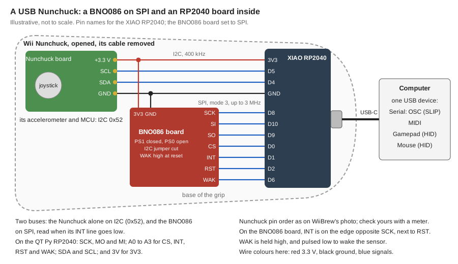
The cost is more wiring and more room: seven signal wires and two supply wires to the BNO086 board, which is 25.4 × 30.5 mm, four wires to the Nunchuck's board, and a microcontroller beside them in the base of the grip, its USB-C port where the cable came out.
Materials
| Item | Amazon | Adafruit | SparkFun | Seeed Studio | Mouser |
|---|---|---|---|---|---|
| A wired Wii Nunchuck | 342 | 485-342 | |||
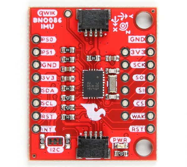 | SEN-22857 | 474-SEN-22857 | |||
| Seeed Studio XIAO RP2040: 21 × 17.8 mm; USB-C; 11 pins | 102010428 | 713-102010428 | |||
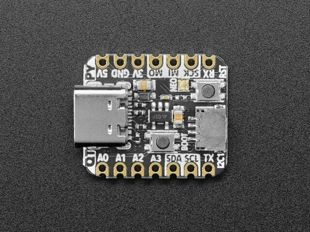 | 4900 | 485-4900 |
| Item | Amazon |
|---|---|
| A USB-C cable to the computer | |
| Thin, flexible insulated wire, in several colours | |
| Two 10 kΩ resistors, if the Nunchuck's board has no I2C pull-ups (see the instructions) | |
| Polyimide (Kapton) tape, to insulate the backs of the boards, and double-sided foam tape to hold them |
Tools
- A tri-point Y0 screwdriver, for the two screws on the Nunchuck's back (iFixit's guide uses one)
- A spudger or a thin plastic pry tool
- A soldering iron with a fine tip, and solder
- A hobby knife, to cut a jumper's trace
- Flush cutters and wire strippers
- A multimeter with continuity and resistance ranges
- The Arduino IDE, with the Arduino-Pico core
Skills
- Soldering fine wires to small pads
- Closing and cutting solder jumpers
- Using a multimeter's continuity and resistance ranges
- Wiring SPI and I2C
- Programming an MCU in Arduino
- USB device classes: serial (CDC), MIDI and HID
Instructions
- Set the BNO086 board to SPI. SPI needs both protocol-select pins high when the sensor resets (Figure 1-5 of CEVA's datasheet; SparkFun's hookup guide). On the board's back, close the PS1 jumper with a blob of solder, but leave PS0 open: its jumper would tie the PS0/WAKE pin straight to 3.3 V (the board's schematic), and the datasheet wants that pin on a microcontroller pin, held high through reset and free afterwards to wake the sensor. On the board's front, cut the trace of the I2C jumper, as the schematic says: "Clear I2C Jumper when using SPI or UART". Leave the ADR jumper on the back open: closed, it ties SI to ground (the schematic).
- Try it on the bench before it goes inside. Wire the BNO086 board to the XIAO RP2040: 3V3 to 3V3, GND to GND, SCK to D8, SI to D10, SO to D9, CS to D0, INT to D1 (INT is on the board's other edge from SCK, next to RST), RST to D2 and WAK to D6. On the QT Py RP2040: 3V3 to 3V, GND to GND, SCK to SCK, SI to MO, SO to MI, CS to A0, INT to A1, RST to A2 and WAK to A3. In the Arduino IDE, install the Arduino-Pico core, choose Tools > USB Stack > Adafruit TinyUSB (Arduino-Pico's USB page), and run the SparkFun BNO08x library's Example_01_SPI_RotationVector with its CS, INT and RST pins changed to these, and two lines added before beginSPI that set the WAK pin as an output and drive it high. SparkFun's example ties PS0 to 3.3 V instead and leaves WAK unconnected.
- Open the Nunchuck: take out the two tri-point screws on its back, and ease the top half of the case off, starting near the joystick, as iFixit's guide shows.
- Find the four points where the cable joins the Nunchuck's board, +3.3 V, SCL, SDA and ground, with the meter's continuity test from the plug's contacts, as in the 9-DoF version. Then free the cable from them, unplugging or unsoldering it, and take the cable and its strain relief out of the shell.
- Check for I2C pull-ups: with the Nunchuck unpowered, measure the resistance from SDA and from SCL to +3.3 V on its board. Measure with the probes both ways round: a resistor reads the same value both ways. If there is none, add a 10 kΩ resistor from each line to 3.3 V, the value Adafruit's Nunchuck adapter uses. Tutorials add pull-ups to 3.3 V outside the Nunchuck: raw.org's Nunchuk driver lists "Pull-up resistors to 3.3V if they are not already present on the adapter", and none of the tutorials read says the Nunchuck's own board has them.
- Before wiring, try both boards in the base: the microcontroller at its end, its USB-C port in the hole the cable leaves, and the BNO086 board beside it.
- Wire the Nunchuck's four points to the microcontroller: +3.3 V to 3V3, ground to GND, SDA to D4 and SCL to D5 on the XIAO (3V, GND, SDA and SCL on the QT Py). Then wire the BNO086 as on the bench, with each wire cut to length.
- Cover the backs of both boards with polyimide tape and fix them with double-sided foam tape, the microcontroller's USB-C port in the hole the cable left, and both boards clear of the screw post. Note which way the BNO086's axes point in the Nunchuck: they are printed on both sides of its board.
- Close the case, and check that the joystick and both buttons still move freely.
- Program it as the Coding Prompt Build Block below describes. Plugged into a computer, the Nunchuck should then appear as a serial port, a MIDI device, a gamepad and a mouse.
- Test each one: a MIDI monitor for the MIDI, the computer's game controller settings for the gamepad, the pointer for the mouse, and Max/MSP or Pd for the OSC (the OSC library's Applications folder has receivers).
- Map them to sound, or play and point with the same controller.
Variations
- Measure the gain: log this Nunchuck's readings and the 9-DoF version's with timestamps, and count the new readings per second from each source.
- Tare: set the present orientation as zero with a button press (the library has a tare example), so that the gamepad's and the mouse's centre follows the way the player holds the Nunchuck.
- Untether it: a Seeed XIAO nRF52840 in place of the RP2040 board has Bluetooth LE and a lithium-ion battery charger, on a board of the same size with the same pins. With a battery in the base it can send MIDI and HID over Bluetooth instead of USB: Adafruit's Bluefruit library, which Seeed's examples for this board use, has blemidi, blehid_gamepad and blehid_mouse examples. A battery only makes sense with a wireless link like this one.
Related resources
- Put a 9-DoF Sensor Inside a Wii Nunchuck: the simpler version, on the Nunchuck's own I2C wires and plug
- SparkFun VR IMU Breakout - BNO086 (Qwiic) Hookup Guide: its pins, jumpers, axes and schematic
- BNO08X Datasheet (CEVA): the SPI connection and timing, protocol selection and the report rates
- USB (Arduino-Pico): choosing the USB stack
- Nunchuk and Extension Controllers (WiiBrew): the Nunchuck's data format, its I2C address and initialisation, and photos of its board and plug
- Wii Nunchuk Joystick and Button Replacement (iFixit): opening the case
- Wiimote, Nunchuck and Inertial Sensor Hacking for Music and other Interactivity, a 2009 presentation at Hexagram/Concordia, Montreal
Coding Prompt Build Block
A prompt to give a coding assistant, to start the code for this activity. Copy the box, answer its questions about your board and pins, and test what comes back on the bench before you rely on it.
I am building "Make a Wii Nunchuck a USB Controller: a BNO086 on SPI and a Microcontroller Inside", the activity at https://adrianfreed.com/wii-nunchuck-usb-bno086-spi.html.
Write a program for an RP2040 board, a Seeed XIAO RP2040 (or an Adafruit QT Py RP2040), in the Arduino-Pico core with its USB stack set to Adafruit TinyUSB. The board is built into a Wii Nunchuck in place of its cable. It reads the Nunchuck's own circuit board over I2C at 400 kHz, at address 0x52, and a BNO086 over SPI, and it appears to the computer as one USB device with four functions: a serial port, MIDI, a gamepad and a mouse.
Initialise the Nunchuck by writing 0x55 to its register 0xF0 and then 0x00 to its register 0xFB, so its data is unencrypted. Then read its six bytes again and again: the joystick's X and Y, the three 10-bit accelerations, and the C and Z buttons. Time each read with micros().
Talk to the BNO086 with SparkFun's BNO08x library, on the RP2040's second core (setup1 and loop1 in Arduino-Pico). Before anything else, set its WAK pin (D6 on the XIAO, A3 on the QT Py) as an output and drive it high: the board's PS0 jumper is left open, so WAK must be high whenever the sensor resets for it to choose SPI, and the library can reset it by itself. Then call beginSPI with its chip-select, interrupt and reset pins (D0, D1 and D2 on the XIAO; A0, A1 and A2 on the QT Py) and an SPI clock of 3 MHz, the BNO086's maximum. The library waits for the interrupt line to go low before every read and write, and resets the sensor after 500 ms of waiting. So call getSensorEvent only when INT reads low, and before each enableReport wake the sensor: drive WAK low, wait for INT to go low (the datasheet gives 150 microseconds at most; give up after about 1 ms), and drive WAK high again before calling the library. Enable the game rotation vector, or the rotation vector, which adds the magnetometer, with reports every 3 ms (the datasheet's fastest for these is 400 a second), and the calibrated gyroscope; for the lowest latency, try the gyro-integrated rotation vector every 1 ms instead. The BNO086 times out after about 10 ms without an answer and retries, and wants one within a tenth of the fastest report period: measure the time from INT going low to the end of getSensorEvent, and check that it stays under that. When it reports a reset, wake it and enable the reports again. Pass the readings to the first core, which runs USB and reads the Nunchuck, without making the second core wait: for example, a buffer that the first core locks only while it copies it. Do not call the library's enableDebugging, and do not print from the second core.
Make the USB device a composite with Adafruit TinyUSB, on the first core. Serial: OSC framed with SLIP, each message with a timestamp: the joystick, the buttons and the Nunchuck's accelerations, and the BNO086's quaternion, yaw, pitch and roll and angular velocities. MIDI: the joystick and the yaw, pitch and roll as control changes, and C and Z as notes. one HID interface with two reports: a gamepad, with the joystick on X and Y, yaw, pitch and roll on Z, Rz and Rx, and C and Z as buttons 1 and 2; and a mouse, moved by the angular velocity while Z is held, with C as its left button. Have the computer poll the HID interface every 1 ms (setPollInterval), to keep the delay from hand to screen short. Keep the mapping in one table that is easy to change, and send each HID and MIDI report only when its values change.
Count the new readings each source gives per second, the Nunchuck's and each BNO086 report's, and send the counts over OSC, so the gain over the Nunchuck alone can be measured.
Libraries to explore:
- SparkFun BNO08x Arduino Library: reads the BNO080, BNO085 and BNO086 over I2C or SPI, built on CEVA's SH2 driver; beginSPI takes the chip-select, interrupt and reset pins and runs SPI mode 3 at up to 3 MHz; its SPI folder has rotation-vector, reset-check and sleep examples (https://github.com/sparkfun/SparkFun_BNO08x_Arduino_Library)
- WiiChuck: reads Wii extension controllers over I2C (the Nunchuck, Classic Controller, Guitar Hero guitar and drums, DJ Hero, Drawsome tablet and Taiko drums), all mapped into one array of values (https://github.com/madhephaestus/WiiChuck)
- Adafruit TinyUSB for Arduino: makes the board a USB device with several interfaces at once, among them Serial (CDC), MIDI and HID; TinyUSB's gamepad report has six 8-bit axes, a hat and 32 buttons, and its mouse report moves the pointer; setPollInterval sets, in milliseconds, how often the computer asks for HID reports; see the hid_composite, hid_gamepad and midi_test examples (https://github.com/adafruit/Adafruit_TinyUSB_Arduino)
- Arduino-Pico: the Arduino core for RP2040 boards, the Seeed XIAO RP2040 and the Adafruit QT Py RP2040 among them; its Tools > USB Stack menu chooses between its own stack (Serial, Keyboard, Mouse and Joystick, but no MIDI) and Adafruit TinyUSB (https://arduino-pico.readthedocs.io/en/latest/usb.html)
- Arduino MIDI Library: sends and receives MIDI over any serial port, and over USB, Bluetooth or a network through its transports (https://github.com/FortySevenEffects/arduino_midi_library)
- OSC for Arduino (CNMAT): encodes and decodes OSC messages, and sends them over USB or hardware serial (framed with SLIP) or over Ethernet and Wi-Fi UDP; its Applications folder has Max/MSP and Pd examples that receive them (https://github.com/CNMAT/OSC)
Before writing anything, ask me what I am using: the board and its pins, or the software (such as Max, Pd or Python), and check its documentation for what this needs. Put the pin numbers, ranges and other settings in one block at the top, each with a comment. Say which of the libraries above you use, and why. Start with a test that shows the raw readings, so that I can check the wiring and the ranges before the rest.
This activity by Adrian Freed is licensed under Creative Commons Attribution-NonCommercial-ShareAlike 4.0 International (CC BY-NC-SA 4.0): you may share and adapt it with attribution, for non-commercial purposes such as personal projects and teaching, and you must share adaptations under the same licence. Product names and links belong to their suppliers. The photos are not covered by this licence: each keeps the licence named in its credit.