Add Rumble to the USB Nunchuck: a MOSFET and a Pager Motor
Series: alt.ctrl activities; builds on Wii controllers
The Wii Remote can rumble; the Nunchuck that plugs into it cannot (Wikipedia: "The Wii Remote provides basic audio and rumble (vibration) functionality, but the Nunchuk does not"). Once the USB Nunchuck has its own microcontroller inside, one spare pin can add it: a small coin vibration motor, a pager motor, switched by a MOSFET, so that a patch or a game can answer the player in the hand that holds the controller.
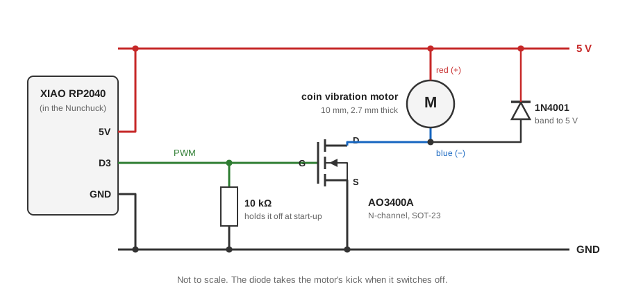
Adafruit's page for this motor suggests a series resistor of 100 to 1000 Ω to run it from a pin at reduced strength, and a small transistor for full power (product 1201); its page for a MOSFET board says such high-current loads "can't be connected directly to a GPIO pin on a microcontroller" (product 5648). The two differ; this recipe follows the second, for full strength from a motor that draws 60 to 100 mA. The motor also kicks back when it switches off. So a MOSFET switches it, a diode takes the kick, and a resistor holds the MOSFET off while the microcontroller starts, as on Adafruit's MOSFET driver board, but with a MOSFET specified to switch fully from the microcontroller's 3.3 V.
Materials
| Item | Amazon | Adafruit | SparkFun | Digi-Key | LCSC |
|---|---|---|---|---|---|
| A coin vibration motor: 10 mm across and 2.7 mm thick, rated 2.5 to 3.8 V; 60 mA at 3 V and 100 mA at 5 V (Adafruit's figures) | 1201 | ||||
| Or SparkFun's vibration motor: 2.3 to 3.6 V, 60 mA at most, with adhesive backing (SparkFun's figures) | ROB-08449 | ||||
| An AO3400A N-channel MOSFET, SOT-23: below 48 mΩ with 2.5 V on its gate, threshold 0.65 to 1.45 V (Alpha & Omega's datasheet) | 785-1000-1-ND | C20917 | |||
| A SOT-23 breakout board, to solder the MOSFET to | 1230 | BOB-00717 | |||
| A 1N4001 diode (any 1N400x), for the motor's kickback | 755 | ||||
| A 10 kΩ resistor, to hold the MOSFET off at start-up | |||||
| A 2.2 µF ceramic capacitor, across the supply, as on Adafruit's board |
| Item | Amazon |
|---|---|
| The USB Nunchuck, built as in Make a Wii Nunchuck a USB Controller | |
| Thin insulated wire, polyimide (Kapton) tape and double-sided foam tape |
Tools
- A soldering iron with a fine tip, and tweezers for the SOT-23 part
- A multimeter
- A coding assistant, given the Coding Prompt Build Block below
- Max/MSP or Pd, and a MIDI app, to send the rumble commands
Skills
- Soldering a small surface-mount part
- Switching a motor with a MOSFET
- Programming with a coding assistant
Instructions
- Solder the AO3400A to the SOT-23 breakout board. Find which of its three legs is the gate (G), the source (S) and the drain (D) in its datasheet before wiring.
- Wire it on the bench to the XIAO RP2040, as in the drawing: D3 to the gate; the 10 kΩ resistor from the gate to GND; the source to GND; the drain to the motor's negative wire (blue on Adafruit's motor); its positive wire (red) to 5V; and the 1N4001 across the motor, its banded end (the cathode) to 5V and its other end to the drain. D3 is free on the USB Nunchuck, which uses D0 to D2, D4 to D6 and D8 to D10, and all of the XIAO's pins can do PWM (Seeed's wiki). The pull-down, the diode across the load and the gate driven straight from the pin are as on Adafruit's MOSFET driver, whose schematic is in its downloads; that board also has a 2.2 µF capacitor across its supply, so put one across 5V and GND near the MOSFET. On another board, such as the QT Py RP2040 or the XIAO RP2040 Plus (whose D3 can be used to measure its battery), use a free PWM pin from its own pinout.
- Run the motor from 5V and keep its average within its rating with the PWM duty, taking the motor to follow the average voltage: Adafruit's disc is rated 2.5 to 3.8 V, so at most 76 % (3.8 ÷ 5), and SparkFun's 2.3 to 3.6 V, so at most 72 % (3.6 ÷ 5). From 5V the motor's current comes from the USB supply rather than the XIAO's own 3.3 V regulator, whose rating Seeed's wiki does not give.
- Try it with a short sketch: analogWrite on D3 sets the strength. Arduino-Pico's PWM runs at 1 kHz by default, and analogWriteFreq changes it if the motor whines (Arduino-Pico's analog output). Check that the motor stays still while the board resets and starts: the 10 kΩ resistor should hold it off.
- Put the motor in the base of the grip, beside the boards: against the inside of the case, where the hand will feel it, and as far from the BNO086 board as the space allows.
- Open the Nunchuck as in the USB Nunchuck, fix the motor in the base with its adhesive backing or double-sided tape, cover the back of the MOSFET board with polyimide tape and fix it with double-sided foam tape, and wire it with thin wire to D3, 5V and GND. Close the case, and check that the joystick and both buttons still move freely.
- Program the commands as the Coding Prompt Build Block below describes: OSC over the serial port and a MIDI control change, each with a strength, and a timeout so that a lost "stop" cannot leave the motor running.
- With the case closed, log the BNO086's readings with the motor running and stopped, to see whether the rumble shows in them. Then send rumble from Max/MSP or Pd, or from a MIDI app, and map it: a pulse for each button press, a buzz that follows a sound's loudness, or a game's hits. Rumble that games send to gamepads is not attempted here.
Variations
- A haptic driver in place of the MOSFET: Adafruit's DRV2605L board drives the same kind of motor over I2C, with built-in effects such as ramps and clicks.
- Two motors, one in the head and one in the base, so the rumble can have a direction (not tried).
Related resources
- Make a Wii Nunchuck a USB Controller: the Nunchuck this adds to
- Adafruit MOSFET Driver: the switch this follows, with its schematic
- AO3400A datasheet: Alpha & Omega's figures for the MOSFET
- Arduino-Pico's analog output: analogWrite and its PWM frequency
Coding Prompt Build Block
A prompt to give a coding assistant, to start the code for this activity. Copy the box, answer its questions about your board and pins, and test what comes back on the bench before you rely on it.
I am building "Add Rumble to the USB Nunchuck: a MOSFET and a Pager Motor", the activity at https://adrianfreed.com/wii-nunchuck-rumble-motor.html.
Help me add rumble to my USB Nunchuck. A Seeed XIAO RP2040 inside it runs the Arduino-Pico core with the Adafruit TinyUSB stack, and already presents a serial port carrying OSC framed with SLIP, USB MIDI, a HID gamepad and a mouse. A coin vibration motor is now switched by an AO3400A MOSFET whose gate is on D3, with a 10 kΩ pull-down and a flyback diode; the motor runs from 5V. Keep everything the firmware already does working.
Drive D3 with analogWrite. Leave the PWM at Arduino-Pico's default 1 kHz unless I ask for another frequency, which analogWriteFreq sets. Keep the duty under a maximum I set in one constant: 76 % for Adafruit's motor disc and 72 % for SparkFun's keep the average within their rated voltage from 5V. Hold D3 low from start-up until the first command, and set it to zero if the USB connection goes away.
Accept /rumble with a strength from 0 to 1 and an optional duration in milliseconds over the serial OSC, and a MIDI control change on a number I choose, its value scaled the same way. Stop the motor when a duration ends, and after a timeout I set if no further command arrives, so a lost message cannot leave it running.
Add a test that needs no computer: if both buttons are held at power-up, pulse the motor once a second until they are released.
Libraries to explore:
- Arduino-Pico analog output: analogWrite drives a pin with PWM; analogWriteFreq sets the frequency (1 kHz by default) and analogWriteRange the range, which loses a bit for each doubling of the frequency (https://arduino-pico.readthedocs.io/en/latest/analog.html)
- Adafruit TinyUSB for Arduino: makes the board a USB device with several interfaces at once, among them Serial (CDC), MIDI and HID; TinyUSB's gamepad report has six 8-bit axes, a hat and 32 buttons, and its mouse report moves the pointer; setPollInterval sets, in milliseconds, how often the computer asks for HID reports; see the hid_composite, hid_gamepad and midi_test examples (https://github.com/adafruit/Adafruit_TinyUSB_Arduino)
- Arduino MIDI Library: sends and receives MIDI over any serial port, and over USB, Bluetooth or a network through its transports (https://github.com/FortySevenEffects/arduino_midi_library)
- OSC for Arduino (CNMAT): encodes and decodes OSC messages, and sends them over USB or hardware serial (framed with SLIP) or over Ethernet and Wi-Fi UDP; its Applications folder has Max/MSP and Pd examples that receive them (https://github.com/CNMAT/OSC)
Before writing anything, ask me what I am using: the board and its pins, or the software (such as Max, Pd or Python), and check its documentation for what this needs. Put the pin numbers, ranges and other settings in one block at the top, each with a comment. Say which of the libraries above you use, and why. Start with a test that shows the raw readings, so that I can check the wiring and the ranges before the rest.
This activity by Adrian Freed is licensed under Creative Commons Attribution-NonCommercial-ShareAlike 4.0 International (CC BY-NC-SA 4.0): you may share and adapt it with attribution, for non-commercial purposes such as personal projects and teaching, and you must share adaptations under the same licence. Product names and links belong to their suppliers.