Replace the Gametrak's Electronics
Series: alt.ctrl activities; builds on Gametrak
The Gametrak's own electronics send HID data over USB, which music software reads directly. Replacing them with your own microcontroller can give a higher update rate, finer resolution, and control over latency and jitter, or cut the cable altogether.
In the paper, a $25 Microchip USB microcontroller board running uOSC sent the data directly as OSC, 1000 times a second. The Wireless Gametrak (2025) puts an ESP32 Feather, a motion sensor and a keypad inside the case, and sends everything over Wi-Fi.
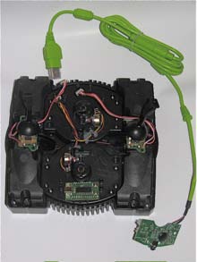
Materials
| Item | Amazon | Adafruit | Mouser | eBay |
|---|---|---|---|---|
| A Gametrak controller (originally sold with two gloves and a footswitch) | search | |||
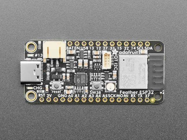 | 5400 | 485-5400 | ||
| For a wireless build: a 3.7 V LiPo battery and an on/off switch | ||||
| Hookup wire |
Tools
- Screwdriver
- Soldering iron
- A rotary tool, for changes to the case (wireless build)
Skills
- Soldering
- Programming an MCU's analog inputs
- Sending OSC messages
Instructions
- Open the Gametrak, then unscrew its circuit board and disconnect it.
- Find each tether sensor's five wires: its three readings (x, y and z), ground, and supply. The Wireless Gametrak lists their colours in its unit.
- Join the two sensors' grounds and supplies to the microcontroller's ground and to the supply its analog inputs measure against (3.3 V on the ESP32 Feather V2), and wire the six readings to six analog inputs.
- Program the microcontroller to read the six inputs and send them as OSC messages, over USB or a network.
- For a wireless build, fit a battery and an on/off switch inside the case. On an ESP32 with Wi-Fi on, use the ADC1 pins: Wi-Fi takes over the ADC2 pins.
- Receive the data in Max/MSP, Pd or other software, and check every axis.
Variations
- Add a motion sensor and a keypad, as the Wireless Gametrak does, for a handheld or two-player instrument.
- Keep the Gametrak's own electronics and remap its USB data instead: see Intervene in USB Controller I/O Streams with an MCU Interposer.
Related resources
- Wireless Gametrak, an Instructable by jekn (2025)
- Musical Applications and Design Techniques for the Gametrak Tethered Spatial Position Controller, Freed and others, SMC 2009, section 4.9
- uOSC: The Open Sound Control Reference Platform for Embedded Devices
- A Low-level Embedded Service Architecture for Rapid DIY Design of Real-time Musical Instruments
Coding Prompt Build Block
A prompt to give a coding assistant, to start the code for this activity. Copy the box, answer its questions about your board and pins, and test what comes back on the bench before you rely on it.
I am building "Replace the Gametrak's Electronics", the activity at https://adrianfreed.com/gametrak-controller-replacement.html.
Write a program for a microcontroller wired in place of a Gametrak's own circuit board: six analog inputs read the two tether sensors' x, y and z, with each sensor's ground and supply joined to the board's ground and to the supply its analog inputs measure against.
Read the six inputs at a steady, high rate, and send them as OSC messages over USB serial or over Wi-Fi, with an address for each axis. On an ESP32 with Wi-Fi on, use ADC1 pins: Wi-Fi takes over the ADC2 pins. Measure and report the update rate and the jitter you achieve.
Libraries to explore:
- ResponsiveAnalogRead: reduces the noise in analog readings without making them sluggish (https://github.com/dxinteractive/ResponsiveAnalogRead)
- OSC for Arduino (CNMAT): encodes and decodes OSC messages, and sends them over USB or hardware serial (framed with SLIP) or over Ethernet and Wi-Fi UDP; its Applications folder has Max/MSP and Pd examples that receive them (https://github.com/CNMAT/OSC)
Before writing anything, ask me what I am using: the board and its pins, or the software (such as Max, Pd or Python), and check its documentation for what this needs. Put the pin numbers, ranges and other settings in one block at the top, each with a comment. Say which of the libraries above you use, and why. Start with a test that shows the raw readings, so that I can check the wiring and the ranges before the rest.
This activity by Adrian Freed is licensed under Creative Commons Attribution-NonCommercial-ShareAlike 4.0 International (CC BY-NC-SA 4.0): you may share and adapt it with attribution, for non-commercial purposes such as personal projects and teaching, and you must share adaptations under the same licence. Product names and links belong to their suppliers.