Add Pressure Sensitivity to Switches
Series: alt.ctrl activities; builds on Button arrays
Many modern buttons use conductive rubber instead of sprung metal to close their contacts. Conductive rubber is piezoresistive.
Materials
| Item | Amazon | Adafruit | Mouser |
|---|---|---|---|
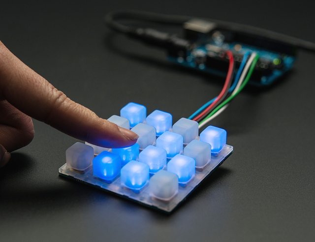 | 1611 | 485-1611 | |
| A microcontroller (MCU) with analog inputs | |||
| Pull-up resistors |
Tools
- Scissors
- Soldering iron
- An MCU IDE
Skills
- Reading an MCU's analog inputs
Instructions
- Switch the role of the MCU inputs the buttons are wired to from digital input to analog-to-digital conversion.
- Add a pull-up resistor to each analog input (most microcontrollers cannot enable a built-in pull-up on an analog input; first-generation Arduinos could).
Variations
- Add appropriately shaped (annular?) pieces of Eeonyx piezoresistive fabric to the switch.

Related resources
- monome
- Pressure Sensing Illuminated Button Array
- eTextile Pressure Sensing Touch Pad
- Favorite eTextile Materials
Coding Prompt Build Block
A prompt to give a coding assistant, to start the code for this activity. Copy the box, answer its questions about your board and pins, and test what comes back on the bench before you rely on it.
I am building "Add Pressure Sensitivity to Switches", the activity at https://adrianfreed.com/add-pressure-sensitivity-switches.html.
Write a program for a microcontroller that reads how hard each key of a 4×4 conductive-rubber keypad is pressed. Conductive rubber is piezoresistive, so read each key on an analog input instead of a digital one, with an external pull-up resistor (most microcontrollers cannot enable a built-in pull-up on an analog input); the reading falls as the key is pressed harder.
If the keys are wired as a matrix rather than one to each input, scan it a row at a time, and explain how you keep keys pressed in other rows from disturbing the reading.
Calibrate each key, at rest and pressed hard, and scale it to a pressure from 0 to 1, with a threshold for a touch. Send each touch as a note whose velocity comes from the pressure, and the pressure that follows as polyphonic aftertouch over MIDI, or send all of it as OSC messages.
Libraries to explore:
- ResponsiveAnalogRead: reduces the noise in analog readings without making them sluggish (https://github.com/dxinteractive/ResponsiveAnalogRead)
- MIDIUSB: makes a board with native USB, such as the Leonardo, Micro, Due or Zero, a USB MIDI device (https://github.com/arduino-libraries/MIDIUSB)
- Arduino MIDI Library: sends and receives MIDI over any serial port, and over USB, Bluetooth or a network through its transports (https://github.com/FortySevenEffects/arduino_midi_library)
- OSC for Arduino (CNMAT): encodes and decodes OSC messages, and sends them over USB or hardware serial (framed with SLIP) or over Ethernet and Wi-Fi UDP; its Applications folder has Max/MSP and Pd examples that receive them (https://github.com/CNMAT/OSC)
Before writing anything, ask me what I am using: the board and its pins, or the software (such as Max, Pd or Python), and check its documentation for what this needs. Put the pin numbers, ranges and other settings in one block at the top, each with a comment. Say which of the libraries above you use, and why. Start with a test that shows the raw readings, so that I can check the wiring and the ranges before the rest.
This activity by Adrian Freed is licensed under Creative Commons Attribution-NonCommercial-ShareAlike 4.0 International (CC BY-NC-SA 4.0): you may share and adapt it with attribution, for non-commercial purposes such as personal projects and teaching, and you must share adaptations under the same licence. Product names and links belong to their suppliers.